 |
|||||||||

Comments
To
check the detector, adjust the zero, attenuation, gain, and balance controls
of the detector and recorder to ensure that the detector signal is being
adequately sent by the detector and processed properly by the recorder.
You should be able to adjust the baseline to 10% full scale and see noise.
If injecting under these conditions does not produce peaks (they will
probably be off scale, however), it suggests that the detector is not
the problem and that for some reason the components are not reaching the
detector.
To check the pump, collect mobile phase exiting the detector to ensure that the delivered flow rate agrees with the value set on the pump controls. If the system uses pumps to generate the mobile phase composition, a low flow rate from one pump can cause the mobile phase composition to be too weak to elute peaks.
Symptom #9 (Continued)
Cause C
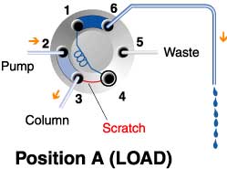
A cross-port scratch on the rotor seal allows mobile phase to leak into the loop while in the LOAD position, displacing sample (see Fig. 31). To confirm: Load the loop with five loop volumes of sample and inject immediately. This should inject at least some sample, even if there is leakage into the loop. Observe the peaks. Load again, but delay injection, allowing time for leakage to displace a significant amount of sample. Inject and observe the peaks. If the peaks are much smaller, it indicates a leak. If the leak is large, you should be able to observe leakage out vent tube #6 while in the LOAD position and with the syringe inserted.Solution
Replace the rotor seal as in Symptom #2 (see comments):
- If none of the above is causing the problem, check that the recorder, detector, and pump are operating properly, and that the mobile phase strength is adequate to elute sample components (see comments).
Fig. 31. View of the rotor seal with the injector in the load position. Mobile phase (lt. blue) pushes sample (blue) out of the loop by leaking along the scratch between ports 3 and 4.
© 2000 Rheodyne All rights reserved